801-613-2759 sale@jfitzelectrical.com

What Are Electrical Protection Methods?

Electricity powers homes, factories, hospitals, and everyday digital systems. Yet invisible energy can create heat, sparks, shocks, or fires within seconds. Electrical protection methods reduce these risks by controlling fault currents and disconnecting unsafe circuits. They also protect equipment from overloads, insulation failure, voltage surges, and accidental contact.

This guide introduces grounding, bonding, fuses, circuit breakers, residual-current devices, surge protection, and protective enclosures. Each method has a specific purpose. A fuse may open during excessive current, while a residual-current device can respond to leakage through an unintended path. Grounding gives fault current a safer route. Insulation creates a physical barrier around conductors. Clear labeling matters too.

Small details matter.

Reliable protection depends on correct design, installation, testing, and maintenance. Qualified professionals should select devices according to system voltage, fault levels, environmental conditions, and manufacturer instructions. Recognized electrical standards and local requirements also provide essential guidance. However, no method is flawless. A breaker cannot correct damaged insulation, and a grounding connection cannot replace careful inspection. Even a well-designed system may become unsafe after moisture, corrosion, vibration, or unauthorized changes.

The sections ahead connect technical principles with practical observations, such as warm outlets, repeated breaker trips, loose connections, and cracked cable jackets. These signs deserve attention, not guesswork. Understanding how protection works helps people ask better questions and recognize when professional assessment is necessary. Safe electrical work is not only about installing devices; it is about verifying that every protective layer still performs when a fault occurs.

What Are Electrical Protection Methods?

Definition and Purpose of Electrical Protection Methods

Electrical protection methods are planned measures that control dangerous electrical energy. They protect people, equipment, and buildings from faults such as short circuits, overloads, earth leakage, and voltage surges. Their purpose is simple: detect abnormal conditions quickly, then disconnect or limit the affected circuit.

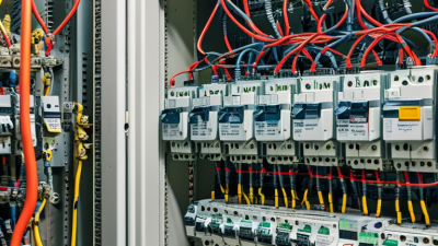
Protection begins with insulation, physical barriers, and correct wiring. A fuse melts when excessive current creates heat. A circuit breaker opens its contacts instead. Grounding and bonding provide a safer path for fault current, helping protective devices operate promptly. Residual-current protection can detect leakage flowing through an unintended path, such as a damaged cable or wet appliance. Surge protection also reduces damage from sudden voltage increases.

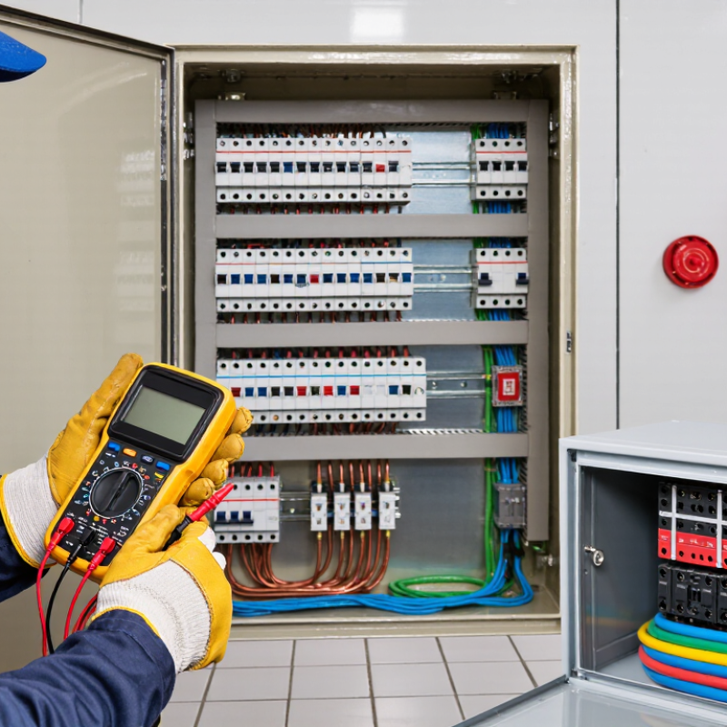
Good protection depends on correct selection and installation. The device must match the conductor size, expected load, fault level, and local electrical requirements. During an inspection, a loose terminal can create heat without immediately tripping a breaker. That detail is easy to miss. Labels, testing, and regular maintenance matter because protection can weaken through corrosion, dust, vibration, or careless modifications. No method is perfect. A breaker may protect wiring but not prevent every electric shock. A grounding system may exist but perform poorly if connections are loose or damaged. Technicians should verify operation with suitable test equipment, record findings, and question assumptions when a system appears normal.

What Are Electrical Protection Methods?

Electrical protection methods are designed to limit the effects of faults such as electric shock, short circuits, and insulation failure. The chart shows the maximum disconnection times specified for automatic disconnection of supply in TN systems under IEC 60364-4-41, based on nominal line-to-earth voltage.

Shorter disconnection times reduce the duration of dangerous touch voltages. Actual protective-device performance depends on the installation design, fault current, and applicable regulations.

Main Types of Electrical Protection Systems

What Are Electrical Protection Methods?

Main Types of Electrical Protection Systems

Electrical protection systems limit damage when current exceeds safe operating conditions. Overcurrent protection uses fuses or circuit breakers to interrupt overloaded or short-circuited circuits. A fuse sacrifices its element. A breaker can usually be reset after inspection. NFPA analysis of 2015–2019 data recorded 32,620 home fires involving electrical distribution and lighting equipment, with 470 deaths and about $1.3 billion in property damage. These figures show why correct ratings and regular testing matter.

Residual-current devices detect leakage flowing toward earth and disconnect power rapidly. They help reduce shock risks, especially in wet areas. Arc-fault protection identifies dangerous arcing patterns before they ignite nearby materials. Surge protective devices divert transient overvoltage from lightning or switching events. Earthing and bonding provide a controlled fault path, while industrial protection relays coordinate breakers across high-current networks. Coordination is crucial.

Small details matter. A loose terminal can create heat behind a quiet panel. Dust, moisture, and aging insulation can weaken protection. The International Electrotechnical Commission stresses verification, testing, and maintenance through its low-voltage installation standards. Yet a compliant installation can still fail when settings are outdated or equipment is modified without review. That is the uncomfortable part. Protection is not a single device; it is a maintained system involving design calculations, inspection records, and trained judgment.

What Are Electrical Protection Methods? - Main Types of Electrical Protection Systems
Protection Method Primary Purpose Operating Principle Typical Protective Devices Commonly Protected Equipment or Areas Main Benefits Important Limitations Protection Role
Overcurrent Protection Protects conductors and equipment from excessive current caused by overloads or short circuits. The protective device opens the circuit when current exceeds a defined rating or time-current characteristic. Fuses, miniature circuit breakers, molded-case circuit breakers, and power circuit breakers. Branch circuits, feeders, distribution panels, transformers, motors, and general wiring systems. Limits thermal damage, reduces fire risk, and clears short-circuit faults quickly. It may not provide adequate protection against low-level arcing or current flowing through a person to ground. Primary
Overload Protection Prevents equipment and conductors from overheating during sustained excessive loading. Detects current above the normal operating value over a period of time and disconnects the circuit after an intentional delay. Thermal overload relays, electronic overload relays, and circuit breakers with adjustable trip units. Electric motors, pumps, fans, compressors, conveyor systems, and industrial control panels. Protects motor windings and cables while allowing temporary starting or inrush currents. It is not intended to replace fast short-circuit protection and may require correct adjustment for the load. Primary
Short-Circuit Protection Clears high-fault currents produced by unintended low-impedance connections between conductors. A fuse or circuit breaker interrupts the fault current before it causes unacceptable thermal, mechanical, or arc damage. High-interrupting-capacity fuses, circuit breakers, current-limiting fuses, and protective relays. Switchboards, busbars, transformers, feeders, motor circuits, and industrial power systems. Provides rapid fault clearing and helps limit arc energy and equipment destruction. Correct device interrupting rating and coordination must match the prospective short-circuit current. Primary
Earth-Fault Protection Detects unintended current flowing from an energized conductor to earth or exposed conductive parts. Senses residual or zero-sequence current and disconnects the affected circuit when the detected value exceeds the setting. Residual-current relays, ground-fault circuit interrupters, earth-leakage relays, and ground-fault protective breakers. Low-voltage distribution systems, industrial installations, generators, transformers, and equipment with grounded enclosures. Reduces fire risk and limits damage from insulation failure or contact with grounded metalwork. Settings must balance sensitivity, selectivity, and immunity to normal leakage currents. Primary
Residual-Current Protection Provides additional protection against electric shock and leakage-related fire hazards. Compares current in the live conductors; an imbalance indicates current returning through earth or another unintended path. Residual-current devices, residual-current circuit breakers, and residual-current circuit breakers with overcurrent protection. Socket-outlet circuits, wet locations, portable equipment, outdoor circuits, and residential final circuits. Can disconnect a circuit at leakage levels much lower than conventional overcurrent devices. It does not replace protective earthing or overcurrent protection, and nuisance tripping can occur with cumulative leakage. Supplementary
Arc-Fault Protection Reduces the risk of fires caused by hazardous electrical arcing. Analyzes the electrical waveform for characteristics associated with series or parallel arcing and disconnects the circuit when necessary. Arc-fault detection devices and arc-fault circuit interrupters. Residential branch circuits, older wiring systems, sleeping areas, and locations where damaged cables may be present. Detects some dangerous arcing conditions that may not create enough current to trip a standard circuit breaker. Performance can be affected by harmless electrical noise, motor loads, and unusual equipment waveforms. Supplementary
Surge Protection Limits transient overvoltages caused by lightning, switching operations, or utility disturbances. Diverts or clamps excess voltage to a safe path, usually through voltage-dependent components or discharge devices. Surge protective devices, metal-oxide varistors, gas discharge devices, and coordinated surge arresters. Service entrances, distribution boards, control systems, communication equipment, and sensitive electronic loads. Reduces insulation stress and helps protect electronic equipment from short-duration voltage surges. It does not regulate sustained overvoltage and requires suitable earthing, wiring length, and energy ratings. Supplementary
Overvoltage and Undervoltage Protection Protects equipment from supply voltage conditions outside its permissible operating range. Measures system voltage and disconnects or alarms when voltage remains above or below defined limits. Voltage-monitoring relays, protective relays, automatic voltage regulators, and control-system interlocks. Motors, control panels, data-processing equipment, generators, and sensitive electronic systems. Helps prevent motor overheating, malfunction, contactor dropout, and damage to electronic components. Thresholds and time delays must be selected carefully to avoid trips during normal voltage fluctuations. Primary
Phase-Failure and Phase-Sequence Protection Protects three-phase equipment from phase loss, incorrect phase rotation, or severe phase imbalance. Monitors phase voltages and their sequence, then trips or inhibits operation when an abnormal condition is detected. Phase-monitoring relays, motor-protection relays, and electronic motor controllers. Three-phase motors, pumps, compressors, refrigeration systems, and process machinery. Prevents reverse rotation, overheating, loss of torque, and mechanical or process damage. It does not by itself protect against every overload, short circuit, or internal motor fault. Primary
Differential Protection Detects internal faults within a defined protected zone, such as a transformer, generator, or busbar. Compares current entering and leaving the protected zone; a significant difference indicates an internal fault. Current transformers, differential relays, and numerical protection relays. Power transformers, generators, motors, busbars, and high-voltage transmission equipment. Provides fast and selective clearing of serious internal faults. Requires accurate current-transformer performance, correct wiring, and careful relay coordination. Primary
Distance Protection Protects transmission lines and other high-voltage circuits from phase and earth faults. Estimates the electrical impedance between the relay location and the fault; impedance generally decreases as the fault gets closer. Distance relays and multifunction numerical line-protection relays. High-voltage and extra-high-voltage transmission lines. Offers rapid fault detection and can provide multiple protection zones along a line. Accuracy can be influenced by fault resistance, power swings, line configuration, and instrument-transformer errors. Primary
Thermal Protection Prevents damage caused by excessive temperature in electrical equipment. Uses temperature sensors or calculated thermal models to initiate an alarm, load reduction, or trip. Thermistors, resistance temperature detectors, thermal switches, and temperature-monitoring relays. Motors, transformers, battery systems, power electronics, cables, and generator windings. Responds directly to heat and can identify overheating caused by conditions other than overcurrent. Sensor placement, response time, and thermal inertia can affect how quickly protection operates. Primary
Insulation Monitoring Identifies declining insulation resistance in systems where an immediate ground-fault trip may be undesirable. Continuously measures insulation resistance between live conductors and earth and provides an alarm or trip. Insulation-monitoring devices and insulation-resistance monitoring relays. Ungrounded or high-resistance-grounded systems, medical locations, mining systems, and critical industrial installations. Can warn of the first insulation fault before a second fault creates a dangerous short circuit. It requires suitable system design and may not provide the same function as conventional residual-current protection. Supplementary
Protective Earthing and Bonding Provides a low-impedance fault-current path and keeps exposed conductive parts near earth potential. Connects exposed metalwork to a protective conductor and earth electrode system so protective devices can operate during a fault. Protective conductors, main bonding conductors, earth electrodes, equipotential bonding, and earthing terminals. Buildings, industrial installations, switchgear enclosures, appliances, and metallic services. Reduces touch voltage and supports reliable operation of fault-protection devices. It is not a switching device; continuity, impedance, corrosion resistance, and periodic testing are essential. Primary
Backup and Selective Protection Maintains system safety when the primary protective device fails or when only the faulted section should disconnect. Uses coordinated protective devices, time grading, current grading, or redundant protection paths. Backup fuses, upstream circuit breakers, coordinated protective relays, and redundant trip circuits. Industrial distribution networks, substations, critical facilities, and large commercial installations. Improves system continuity, limits the outage area, and provides additional fault-clearing reliability. Requires accurate fault studies, coordination settings, maintenance, and periodic verification. Primary

How Electrical Protection Devices Detect Faults

Electrical protection devices detect faults by measuring abnormal current, voltage, or leakage. A circuit breaker reacts when current exceeds its thermal or magnetic threshold. The thermal element responds to sustained overloads. The magnetic element trips rapidly during short circuits. A residual-current device compares outgoing and returning current. Even a small imbalance can open the circuit within milliseconds.

Arc-fault protection examines the electrical waveform for irregular noise and repeated interruptions. These signals can indicate a damaged cable, loose terminal, or overheated connection. NFPA’s Home Fires Involving Electrical Distribution and Lighting Equipment report estimates 32,650 U.S. home fires annually from 2015 to 2019. Those fires caused about 470 civilian deaths, 1,100 injuries, and 1.3 billion dollars in direct property damage. Detection speed matters.

Protection is not automatic perfection. A breaker can be correctly rated and still miss a high-resistance connection. A leakage device may also fail when testing is ignored. IEC 60364-4-41 emphasizes automatic disconnection, protective earthing, and coordinated device selection. In commissioning, technicians should verify trip settings, conductor size, fault-loop impedance, and selectivity. A simple test button is useful. It is not enough. Fault records from the IEEE 1584 approach also show why available fault energy and clearing time require site-specific assessment. Real installations contain dust, vibration, moisture, and aging insulation. Devices detect patterns, but maintenance determines whether protection remains dependable.

Applications in Residential, Commercial, and Industrial Settings

What Are Electrical Protection Methods?

Applications in Residential, Commercial, and Industrial Settings

Electrical protection methods reduce harm from overloads, short circuits, leakage currents, and voltage surges. In homes, circuit breakers disconnect overloaded circuits before cables overheat. Residual-current protection can detect leakage near bathrooms, kitchens, and outdoor outlets. Grounding gives fault current a controlled path. Surge protection also helps protect sensitive electronics during unstable supply conditions.

Commercial buildings require more coordination. A fault on one office circuit should not shut down an entire floor. Engineers often separate lighting, power, elevators, fire systems, and essential equipment. Selective protection helps the nearest device operate first. Regular testing matters, especially for emergency lighting and protective disconnection systems. A poorly labeled panel can delay maintenance and create avoidable risk.

Industrial facilities face higher fault energy and more complex machinery. Motor overload relays, short-circuit protection, isolation devices, and ground-fault protection work together around pumps, conveyors, and control cabinets. Arc-flash assessments can guide equipment settings, boundaries, and protective clothing. Local codes, environmental conditions, and equipment ratings must shape every design. No design is flawless. Dust, moisture, aging insulation, or an overlooked modification can defeat a sound plan. Qualified electricians should verify settings, inspect connections, and document changes. The assumption that “it worked last year” deserves review.

Selection and Maintenance of Electrical Protection Methods

What Are Electrical Protection Methods?

Selection and Maintenance of Electrical Protection Methods

Electrical protection methods reduce the risks of shock, fire, and equipment damage. Common measures include circuit breakers, fuses, grounding, insulation, and residual-current protection. Each method addresses a different failure condition. A fuse may stop excessive current, while grounding provides a safer path for fault energy.

Electrical protection methods reduce the risks of shock, fire, and equipment damage.

Selection should begin with the installation’s voltage, load, fault level, environment, and expected future demand. Moisture, dust, heat, vibration, and corrosive chemicals can change the decision. Protective devices must match cable capacity and disconnect quickly during faults. A qualified electrician should verify calculations, coordination, and local requirements. A neat control panel is not enough.

A neat control panel is not enough.

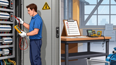
Maintenance requires more than pressing a test button. Inspectors should check loose terminals, damaged insulation, overheating marks, corrosion, and blocked ventilation. Test results should include dates, measured values, and corrective actions. In practical inspections, small temperature differences around terminals often deserve attention. They may indicate a developing connection problem. I once underestimated the importance of clear labels; later, troubleshooting took longer than expected. That mistake still influences my inspection routine.

Protection settings should be reviewed after machinery, wiring, or operating conditions change. Testing intervals depend on risk, equipment type, and applicable regulations. Never bypass a protective device to keep production running. It can hide a fault and increase danger. Records should remain readable, complete, and available to the people responsible for safe operation.