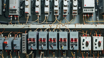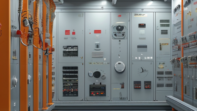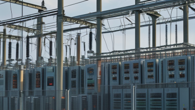
Electrical system protection is the set of methods and devices that detect electrical faults and limit their effects. It helps protect people, equipment, and the continuity of power. A fault may begin as a short circuit, an overloaded conductor, or damaged insulation. Left unchecked, excess current can heat wires, damage motors, or start a fire. That matters.
Protection is not one device acting alone. Fuses and circuit breakers interrupt current, while protective relays monitor conditions and signal breakers when abnormal behavior appears. Grounding provides a path for certain fault currents and helps reduce dangerous voltage differences. In a well-designed installation, these elements work together so the affected section can be isolated without unnecessarily shutting down the whole system. Small details count.
This guide explains the core principles behind electrical system protection, including common protective devices, fault detection, and coordination. It also considers how designers and maintenance teams assess risks, inspect equipment, and choose settings suited to a system’s load and layout. Good protection is planned. It is also tested and reviewed as equipment changes. Still, no arrangement is perfect: incorrect settings, worn components, or overlooked operating conditions can weaken performance. That is worth remembering. Understanding both the safeguards and their limits gives readers a practical foundation for evaluating how electrical systems respond when something goes wrong.
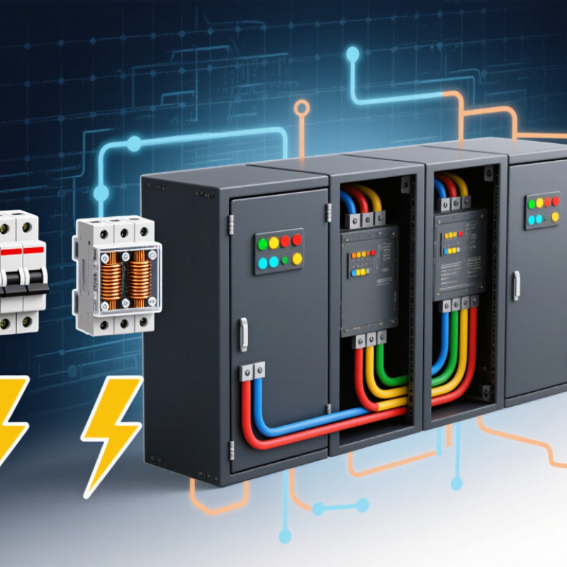
Electrical system protection is the coordinated use of sensors, protective relays, circuit breakers, fuses, and grounding to detect abnormal electrical conditions and limit harm. A relay may detect a short circuit in milliseconds; a breaker then opens the affected circuit. The goal is selective isolation: disconnect the faulty branch while keeping unaffected equipment energized. That distinction matters. Protection is not simply shutting everything down.
The U.S. Energy Information Administration’s Electric Power Annual 2022 reports average customer interruption duration of about 5.5 hours when major event days are included, compared with about 2.3 hours when they are excluded. These figures describe outage duration, not the performance of protection devices, but they show why continuity matters.
In a workshop, a properly coordinated system can keep a motor fault from darkening an entire floor.
Settings must match actual load, available fault current, and equipment ratings; old drawings or changed machinery can undermine that match. Protection is not magic. A relay set too sensitively may trip during normal starts, while a slow or poorly coordinated device may allow damage to spread. Regular testing and updated records help, though they cannot remove every risk.
Electrical systems need protection because wires and equipment can fail under abnormal conditions. A damaged cable, overloaded circuit, or loose connection can create heat, interrupt service, or start a fire. Circuit breakers and fuses limit current by disconnecting a faulty circuit. Ground-fault devices can reduce shock risk in areas where moisture is common. Surge protection can help shield sensitive electronics from brief voltage spikes. The right combination depends on the building, its loads, and local requirements.
That matters.
Protection also helps keep one fault from affecting an entire building. A properly coordinated system can isolate a problem while other circuits continue to operate. Still, protection is not magic; devices may be incorrectly selected, worn, or poorly maintained. A panel can look tidy while hidden wiring remains damaged. Small details count. Qualified electricians can inspect connections, confirm protective devices suit the installation, and identify changes after renovations or added equipment. Regular checks are easy to postpone, and that is an uncomfortable weakness in many maintenance plans. Clear circuit labels and accurate records also help people respond safely when a fault occurs.
Electrical protection depends on sensors and devices acting together, often within milliseconds. Current transformers measure feeder current, while voltage transformers track system voltage. Protective relays compare these signals with preset limits and issue a trip command when they detect abnormal conditions. A circuit breaker then opens its contacts to stop current flow. For simpler circuits, a fuse melts and breaks the path when current exceeds its rating.
Different faults call for different methods. Ground-fault protection looks for current leaking from its intended path; differential protection compares current entering and leaving equipment, such as a transformer. Arc-flash relays may combine light sensors with overcurrent measurements to trigger a fast interruption. The U.S. Energy Information Administration’s Electric Power Annual reported average customer interruption durations of about 5.6 hours in 2022, including major events, and about 2.5 hours excluding them. Those figures describe reliability, not protection-device performance, but they show why dependable fault isolation matters. Timing matters. Relay settings must coordinate so the nearest breaker trips first, while upstream protection remains available if it fails. Still, a setting that looks sound in a study may behave differently in a crowded, aging switchboard. Field testing deserves more attention. No device is perfect.
| Protection Device | What It Detects | How It Responds | Typical Applications | Important Note |
|---|---|---|---|---|
| Fuse | Excess current caused by an overload or short circuit. | A fusible element heats and melts when current exceeds its rating, opening the circuit. | Branch circuits, equipment, control circuits, and many electronic devices. | Once operated, a fuse must be replaced with the correct type and rating. |
| Circuit Breaker | Overcurrent, including overloads and short circuits; some models also detect ground faults or arc faults. | Trips its contacts open to interrupt current. Depending on its design, it may be reset after the fault is cleared. | Residential, commercial, and industrial distribution systems. | Its interrupting rating must be suitable for the available fault current at the installation point. |
| Protective Relay | Abnormal electrical conditions such as overcurrent, undervoltage, differential current, or frequency deviation. | Analyzes measurements from instrument transformers and sends a trip signal to a circuit breaker. | Generators, transformers, motors, feeders, and transmission lines. | A relay detects and commands protection; a separate switching device usually interrupts the power circuit. |
| Residual-Current Device (RCD/RCCB) | An imbalance between current flowing through the live conductors, which can indicate current leaking to earth. | Disconnects the circuit when the residual current reaches its specified operating threshold. | Personal shock protection and additional protection against certain earth-leakage hazards. | A basic RCD does not necessarily provide overload or short-circuit protection; coordinated overcurrent protection may also be required. |
| Ground-Fault Circuit Interrupter (GFCI) | A small difference between outgoing and returning current that may indicate current flowing through an unintended path. | Rapidly opens the circuit when its ground-fault detection threshold is reached. | Locations where electrical equipment may be exposed to moisture, as required by applicable electrical codes. | It is intended to reduce shock risk and is not a substitute for all forms of overcurrent protection. |
| Arc-Fault Circuit Interrupter (AFCI) | Electrical signatures associated with certain hazardous arcing faults in wiring or connected equipment. | Recognizes qualifying arc patterns and trips the circuit to reduce the risk of fire. | Selected residential and other circuits where arc-fault protection is required by local code. | It complements, rather than replaces, standard overcurrent protection. |
| Thermal Overload Relay | Sustained motor overcurrent that can cause excessive heating, often due to overload or phase loss. | Opens the motor-control circuit, typically causing a contactor to disconnect the motor. | Motor starters and motor-control assemblies. | It protects against sustained overload conditions; short-circuit protection is generally provided by a separate device. |
How Protection Coordinates Across an Electrical Network
Electrical protection works as a coordinated set of devices, not as isolated switches. Relays monitor current and voltage, then signal circuit breakers when readings indicate a fault. The goal is to disconnect only the affected section while keeping healthy parts of the network energized. That matters.
For example, if a cable develops a short circuit, the nearest protection device should usually trip first. Upstream devices are set to allow a brief delay, so they can act as backup if the local breaker fails. Engineers compare operating times and fault-current levels when selecting these settings. A poorly matched delay can cut power to more customers than necessary.
Coordination must reflect the actual network, including transformers, cable lengths, and changes in how equipment is connected. A protection study can model likely faults and check whether devices respond in the intended order. Field testing also matters: a setting that looks correct on a diagram may not perform as expected in service. In practice, coordination is not perfectly tidy; networks change, and protection settings need review after significant upgrades or operating changes.
What Is Electrical System Protection?
Where Protection Systems Are Applied and Maintained
Electrical protection is installed wherever faults could damage equipment or endanger people: service entrances, switchboards, transformers, motor-control centers, and backup-power systems. Fuses, circuit breakers, protective relays, and grounding work together to detect abnormal current and isolate the affected section. In a plant, that may mean a relay trips one feeder while the rest of the line keeps running. Small details matter. A mislabeled breaker can slow a response.
Maintenance keeps those devices dependable. Technicians inspect connections, test breaker operation and relay settings, check grounding, and review coordination after equipment changes. Infrared scans can reveal a hot terminal before it fails, though a scan cannot identify every hidden defect. The U.S. Bureau of Labor Statistics recorded 145 fatal work injuries involving exposure to electricity in 2022. This figure does not show that protection systems failed, but it underscores why safe work practices and functioning safeguards matter (National Census of Fatal Occupational Injuries in 2022).
Tips: Keep one current protection-setting record. Test devices at intervals suited to their condition and environment. Dust, heat, vibration, and hurried modifications all matter. A checklist helps, but it cannot replace a careful inspection.
How to read it: Protective relays monitor electrical quantities and signal a circuit breaker when they detect a fault. This conceptual 60 Hz waveform shows normal current, a higher fault current, and current falling to zero after interruption. Actual fault levels and clearing times depend on the system, relay settings, and breaker performance; this is not a field measurement.