
801-613-2759 sale@jfitzelectrical.com

How to Choose Barite Drywall for Radiation Shielding?

Choosing Barite Drywall Radiation Shielding requires more than comparing board thicknesses. Medical imaging rooms produce different radiation levels, workloads, and exposure patterns. The UNSCEAR 2020/2021 Report identifies medical exposure as the largest artificial source of ionizing radiation for many populations. That finding makes practical shielding design increasingly important in hospitals, dental clinics, and diagnostic centers.

Barite drywall combines gypsum board with barium sulfate, a dense mineral commonly measuring about 4.2 to 4.5 g/cm³ in raw form. However, finished-panel density can vary by manufacturer, moisture content, and production method. Confirm the tested density. Do not rely only on product brochures. NCRP Report No. 147 explains that shielding depends on workload, use factor, occupancy, distance, and radiation energy. IAEA Safety Reports Series No. 47 also stresses room-specific calculations for radiotherapy facilities. These references support a measured approach, not a universal thickness rule.

On practical projects, installers should check panel joints, service penetrations, door frames, and wall-to-ceiling connections. A small unshielded gap can undermine an otherwise dense barrier. That detail is easy to miss. Designers should request independent attenuation data, declared lead-equivalence values, fire performance, and installation instructions. Local radiation-safety professionals must review the final design under applicable regulations. Barite Drywall Radiation Shielding can be efficient, clean, and easier to install than some traditional systems. Still, it is not automatically the best option. Actual room conditions decide that. A stronger article should also admit uncertainty: manufacturer test conditions may not perfectly represent every clinical installation. Field verification and documented quality control remain essential.
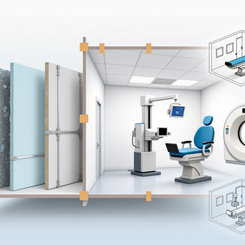
How to Choose Barite Drywall for Radiation Shielding?

Identify the Radiation Source and Energy Range: Diagnostic X-Rays Commonly Use 40–150 kVp

How to Choose Barite Drywall for Radiation Shielding?

Start by identifying the radiation source and its energy range. Diagnostic X-ray systems commonly operate between 40 and 150 kVp, according to the International Atomic Energy Agency’s Diagnostic Radiology Physics handbook. Dental imaging may use lower settings, while general radiography and fluoroscopy often approach the upper range. A 100 kVp beam does not mean every photon has 100 keV. The spectrum contains many lower-energy photons, and filtration changes its penetration.

Barite drywall should therefore be selected from the actual workload, not from kVp alone. Record examinations per week, exposure time, tube current, beam direction, room occupancy, and the distance to nearby areas. NCRP Report No. 147 and IAEA Safety Reports Series No. 47 both emphasize these factors in diagnostic shielding design. A busy fluoroscopy room may need a different barrier strategy from a lightly used radiography room, even at similar kVp.

Measure carefully.

Barite panels provide mass and attenuation, but their performance depends on density, thickness, joints, penetrations, and installation quality. Site experience shows that poorly sealed seams can weaken an otherwise heavy wall. The required thickness should be calculated by a qualified medical physicist using the manufacturer’s verified attenuation data and local design goals. One practical weakness remains: early planning often relies on estimated workloads. Review those estimates after commissioning, because real clinical use may change quickly.

How to Choose Barite Drywall for Radiation Shielding?

Identify the radiation source and energy range before selecting shielding materials. The chart shows representative tube-voltage ranges used in common diagnostic X-ray applications. Diagnostic radiography commonly operates within approximately 40–150 kVp.

kVp indicates the maximum tube potential and is not the sole basis for shielding thickness. Final barite drywall design should also consider workload, distance, occupancy, beam direction, room geometry, and applicable radiation-protection regulations.

Verify Barite Drywall Density: Typical Products Range from 2.8–3.5 g/cm³

How to Choose Barite Drywall for Radiation Shielding?

Barite drywall is selected by density, thickness, and tested shielding performance. Typical products range from 2.8–3.5 g/cm³. Higher density usually means more barite content and stronger attenuation per panel. However, density alone does not determine protection. Panel thickness, joints, penetrations, and the radiation source also matter. A 3.5 g/cm³ board may not perform well if seams are poorly sealed. Small gaps can become serious weak points.

Tips:

Request a current density certificate for each production batch. Check the measured value, not only the advertised range. Weigh a sample when practical, then compare its dimensions with the supplier’s data. Inspect edges for cracks, voids, or uneven surfaces. Ask a qualified radiation-protection professional to calculate the required thickness.

On site, installers should stagger joints and avoid aligning openings on opposite sides. Use compatible joint materials with documented density and strength. Do not assume ordinary gypsum screws or filler will preserve the barrier. Service openings require careful detailing. This part is often overlooked. I would also allow a small inspection area before full installation. It may reveal inconsistent density or fragile edges. Product labels can look convincing, yet independent testing remains more reliable. Radiation surveys should verify the completed room before occupancy. A perfect calculation cannot correct careless installation.

Compare Areal Density, Not Thickness Alone: 1 mm of Lead Equals 11.34 kg/m²

How to Choose Barite Drywall for Radiation Shielding?

Choose barite drywall by areal density, not thickness alone. Areal density means the panel’s mass per square metre. It reflects how much shielding material occupies the radiation path. A thicker panel may perform poorly if its density is low. A compact, dense panel can provide stronger attenuation with less wall buildup.

Use lead as a practical reference. One millimetre of lead weighs 11.34 kg/m². Therefore, a design target of 22.68 kg/m² represents the mass of 2 mm of lead, before considering material-specific performance.

Barite drywall should be evaluated by its measured density, thickness, and radiation attenuation data. Do not treat lead equivalence as a simple thickness conversion. Energy level matters.

Small details often decide the result. Check panel weight, joint layout, screw spacing, and overlaps around doors or service penetrations.

A gap beside a conduit can weaken an otherwise heavy wall. Corners need careful detailing. The supporting structure must also carry the added load safely. This part is often underestimated.

The comparison is not perfect. Barite distribution can vary between products and batches. A qualified radiation physicist should verify the design using the actual equipment, workload, distance, and room layout.

Request independent test data when possible. Recheck the assumptions. A neat calculation can still miss a weak seam.

Specify Required Lead Equivalence Using NCRP 147 and Local Shielding Codes

Selecting barite drywall begins with the radiation design, not the board thickness. NCRP Report No. 147 requires shielding calculations based on workload, beam energy, use factor, occupancy, distance, and the design goal. These variables can change the required lead equivalence significantly. A general-purpose “one-inch board” specification is therefore unreliable.

Ask the medical physicist to state the target in millimeters of lead equivalence at a defined energy, such as 0.5 mm Pb at 100 kVp. The specification should also identify primary or secondary barrier use, test conditions, joints, fasteners, and acceptable tolerances. NCRP 147 provides the calculation framework, while local shielding codes and health-authority rules determine approval requirements. IAEA Safety Reports Series No. 47 also emphasizes workload assessment and controlled-area design for diagnostic radiology facilities.

Density alone does not prove performance. Barite drywall should have independent test data showing attenuation under relevant beam qualities. NCRP Report No. 160 reports that medical exposure remains the largest artificial source of public radiation exposure, making verification important. That sounds simple. It is not.

On site, inspect board alignment, penetrations, door frames, and service openings. A small unshielded gap can undermine a carefully calculated barrier. Installation records should match the physicist’s drawings. One practical weakness remains: many specifications copy lead-equivalence values from unrelated test conditions. Review the evidence again before procurement. Local code interpretation may also differ between jurisdictions, so final approval should come from the responsible radiation-safety authority.

How to Choose Barite Drywall for Radiation Shielding? - Specify Required Lead Equivalence Using NCRP 147 and Local Shielding Codes

Design Dimension What to Specify Representative Data or Range Design and Verification Notes
Applicable design standard Use NCRP Report No. 147 as the shielding-calculation framework, together with the applicable local radiation-control, building, fire, and electrical codes. NCRP 147 addresses diagnostic X-ray facilities, including radiography, fluoroscopy, CT, dental, mammography, and related rooms. NCRP 147 does not provide one universal barite-drywall thickness or one universal lead-equivalence value. The required barrier is calculated for the specific room and equipment.
Radiation source and beam quality Identify equipment type, maximum tube potential, filtration, target angle, and whether the barrier receives primary or secondary radiation. Diagnostic X-ray systems commonly operate within approximately 40–150 kVp, depending on the application. CT shielding is normally based on workload and scatter/leakage conditions rather than a single fixed kVp. Lead equivalence is beam-quality dependent. A value verified at one kVp or filtration condition must not automatically be applied to another beam quality.
Barrier classification Classify each wall, floor, ceiling, door, window, and equipment enclosure as a primary or secondary barrier. Primary barrier: may intercept the useful beam.
Secondary barrier: intercepts leakage and scattered radiation.
Primary barriers generally require more shielding than secondary barriers. The barrier category should be confirmed on the approved shielding plan.
Required design goal Specify the permissible weekly dose or design goal at the occupied area beyond the barrier. Common planning values used in shielding practice are approximately 0.1 mSv/week for controlled areas and 0.02 mSv/week for uncontrolled areas, subject to local regulatory requirements. These values are planning examples, not a substitute for the limits or design goals adopted by the local authority having jurisdiction.
Workload Provide the expected workload using the units appropriate to the equipment, such as mA·min/week, patient examinations/week, or CT workload data. Use actual operating records where available. If the installation is new, use a documented conservative estimate approved by the qualified medical physicist. Underestimating workload can result in inadequate shielding. Future workload growth should be considered before the wall system is finalized.
Use and occupancy factor Document the use factor for primary barriers and the occupancy factor for the adjacent area. Occupancy examples include full-time offices or control rooms, partial-time corridors, and low-occupancy storage areas. The correct factor depends on actual use. Do not select a lower shielding level solely because an adjacent space is currently unoccupied if its future use could change.
Distance to occupied area Record the distance from the focal spot or relevant radiation source to the point of occupancy beyond the barrier. Measure the shortest realistic distance for the applicable barrier and room configuration. Distance is a major factor in NCRP-style calculations. A wall serving multiple adjacent spaces should be checked for the most demanding condition.
Required lead equivalence State the calculated minimum lead equivalence for each barrier, including the beam quality and test basis. Typical project specifications may use values such as 0.5 mm Pb, 1.0 mm Pb, 1.5 mm Pb, or higher, but the correct value must come from the shielding calculation. Lead-equivalence values are not interchangeable across kVp, filtration, primary-beam, and secondary-radiation conditions. Specify the required value separately for every barrier type.
Barite drywall material Specify the board thickness, dry density, composition, dimensional tolerance, and tested radiation-attenuation performance. Barite-containing gypsum products are commonly supplied in nominal thicknesses such as 12.7 mm and 15.9 mm; actual product dimensions and densities vary by formulation. Thickness or density alone does not establish lead equivalence. Require a current independent test report or code-recognized product evaluation for the specified beam quality.
Layering strategy Define the number of board layers, orientation, total assembly thickness, and whether additional shielding is required. Multiple layers may be used where one layer does not meet the calculated requirement. The total attenuation must be based on tested assembly performance, not simple thickness multiplication unless justified. Stagger joints between layers and follow the tested installation configuration. Avoid unprotected paths around sockets, ducts, framing, and service penetrations.
Joints, corners, and penetrations Specify continuity of shielding at board joints, internal and external corners, ceiling-to-wall interfaces, floors, doors, windows, outlets, ducts, and cable routes. All discontinuities should provide shielding equal to the adjacent barrier requirement unless the approved design states otherwise. A high-performance wall can fail its design goal if joints or penetrations create direct radiation streaming paths.
Fire, structural, and moisture requirements Confirm wall assembly fire rating, framing capacity, fastener requirements, impact resistance, moisture exposure, and installation tolerances. Barite-containing boards are substantially heavier than ordinary gypsum board; verify wall dead load and handling requirements before construction. Radiation shielding performance does not automatically demonstrate compliance with fire, structural, acoustic, or accessibility requirements.
Installation quality control Require inspection before concealment, photographic records, as-built drawings, and verification of all shielding transitions. Check board count, thickness, joint staggering, fasteners, corner details, penetrations, door and window shielding, and ceiling/floor continuity. Any field change affecting the barrier should be reviewed by the qualified medical physicist or shielding designer before installation is completed.
Acceptance survey Arrange a radiation-protection survey after equipment installation and commissioning. Survey conditions should represent the maximum intended operating parameters and should cover occupied areas outside every shielded boundary. The final survey should be performed and documented by a qualified medical physicist or other person authorized under local regulations.
Recommended specification wording Write the requirement as a performance specification rather than relying only on board thickness. Example: “Provide a continuous barite-containing gypsum wall assembly achieving not less than ___ mm Pb equivalent at ___ kVp under the specified test method and installation configuration.” Insert the blank values only after the NCRP 147 calculation, local-code review, and product-performance verification are complete.
Important: Barite drywall thickness cannot be converted to a universal lead-equivalence value using density alone. Final shielding selection must be based on the calculated workload, beam quality, barrier classification, distance, occupancy, design goal, tested assembly performance, and requirements of the local authority having jurisdiction.

Evaluate Joints, Penetrations, and Installation Quality for Continuous Protection

How to Choose Barite Drywall for Radiation Shielding?

Barite drywall works only when its joints, edges, and penetrations maintain a continuous barrier. NCRP Report 147 states that shielding design depends on workload, use factor, occupancy, distance, and adjacent-area use. A standard board thickness cannot guarantee protection in every room. IAEA Safety Reports Series No. 47 also recommends design verification through site-specific workload and occupancy data. Do not guess.

Installers should stagger board joints between layers and avoid aligned seams at corners. Sealant must remain compatible with the board and resist shrinkage. Small gaps matter. Electrical boxes, ventilation sleeves, plumbing openings, and cable trays require planned shielding details. A metal conduit crossing the wall can create a weak path if its surrounding void remains unprotected. Each penetration should receive an approved, tested treatment that matches the barrier’s required shielding performance.

Quality checks should include board density records, thickness measurements, joint photographs, and inspection before concealment. The American Association of Physicists in Medicine emphasizes documented verification during radiation shielding evaluations. A drawing can still miss a careless cutout. That is an uncomfortable lesson. Independent review, followed by radiation surveys after commissioning, helps confirm the installed room performs as designed. Test results should be retained with the room’s maintenance records.